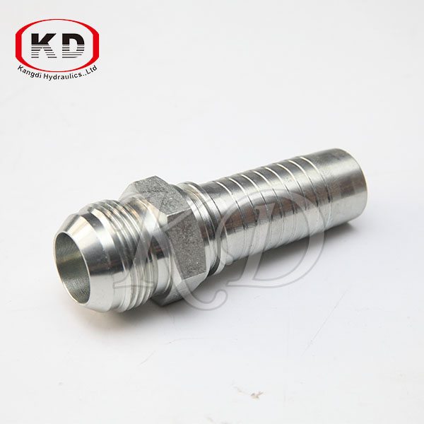
China Wholesale for 15611-PO Sockeless Hose Fitting for Peru Manufacturers
China Wholesale for 15611-PO Sockeless Hose Fitting for Peru Manufacturers Detail:
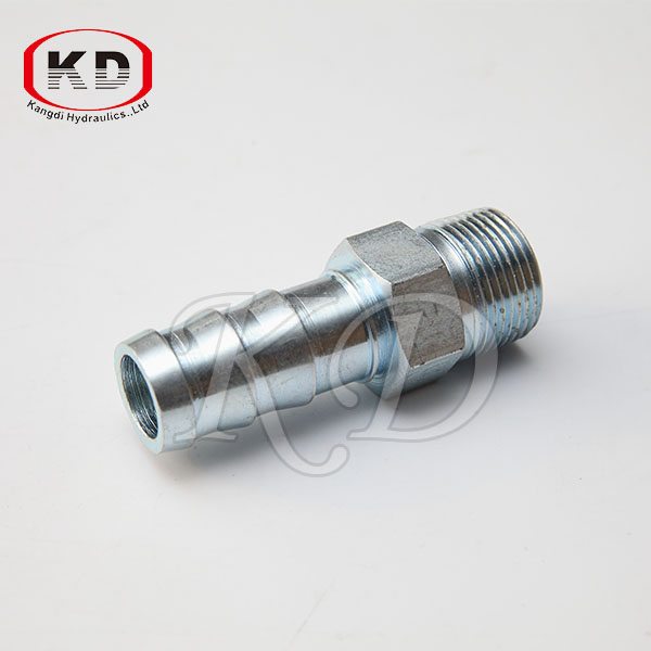
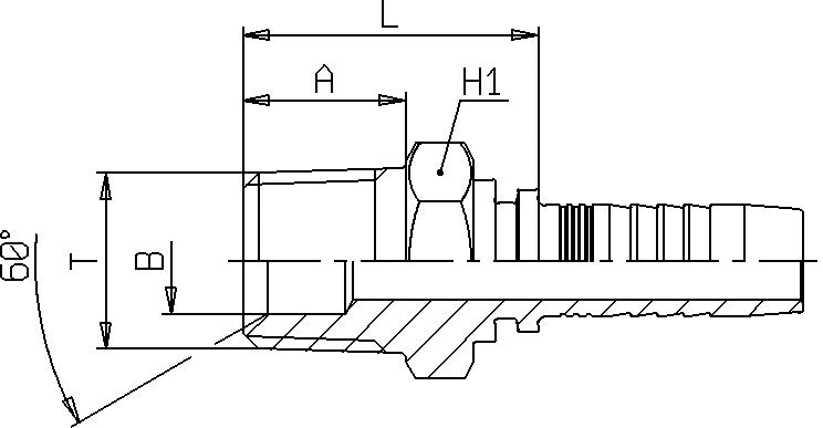
NPTF MALE 60° CONE SEAT
|
PART NUMBER |
HOSE
|
THREAD T |
B mm |
L mm |
A mm |
H1 mm |
||
|
|
DN |
In |
SIZE |
|
|
|
|
|
| S156A0 – 03 – 02 | 4 | 3/16″ | 03 | 1/8″ – 27 | 4 | 23,1 | 10 | 12 |
| S156A0 – 03 – 04 | 4 | 3/16″ | 03 | 1/4″ – 18 | 5,5 | 28,6 | 14,5 | 14 |
| S156A0 – 04 – 02 | 6 | 1/4″ | 04 | 1/8″ – 27 | 4 | 23,5 | 10 | 12 |
| S156A0 – 04 – 04 | 6 | 1/4″ | 04 | 1/4″ – 18 | 5,5 | 29 | 14,5 | 14 |
| S156A0 – 04 – 06 | 6 | 1/4″ | 04 | 3/8″ – 18 | 9,5 | 31,5 | 14,5 | 19 |
| S156A0 – 05 – 04 | 8 | 5/16″ | 05 | 1/4″ – 18 | 5,5 | 29,5 | 14,5 | 14 |
| S156A0 – 05 – 06 | 8 | 5/16″ | 05 | 3/8″ – 18 | 9,5 | 32 | 14,5 | 19 |
| S156A0 – 06 – 04 | 10 | 3/8″ | 06 | 1/4″ – 18 | 5,5 | 30,1 | 14,5 | 17 |
| S156A0 – 06 – 06 | 10 | 3/8″ | 06 | 3/8″ – 18 | 9,5 | 32,1 | 14,5 | 19 |
| S156A0 – 06 – 08 | 10 | 3/8″ | 06 | 1/2″ – 14 | 12,5 | 34,6 | 19,2 | 24 |
| S156A0 – 08 – 06 | 12 | 1/2″ | 08 | 3/8″ – 18 | 9,3 | 32,3 | 14,5 | 19 |
| S156A0 – 08 – 08 | 12 | 1/2″ | 08 | 1/2″ – 14 | 12,5 | 34,8 | 19,2 | 24 |
| S156A0 – 08 – 12 | 12 | 1/2″ | 08 | 3/4″ – 14 | 16 | 39,8 | 19,2 | 27 |
| S156A0 – 10 – 08 | 16 | 5/8″ | 10 | 1/2″ – 14 | 12 | 38,8 | 19,2 | 24 |
| S156A0 – 10 – 12 | 16 | 5/8″ | 10 | 3/4″ – 14 | 16 | 39,8 | 19,2 | 27 |
| S156A0 – 12 – 12 | 20 | 3/4″ | 12 | 3/4″ – 14 | 16 | 40,5 | 19,2 | 27 |
| S156A0 – 12 – 16 | 20 | 3/4″ | 12 | 1″ – 11,5 | 19,5 | 45,5 | 24,2 | 36 |
| S156A0 – 16 – 16 | 25 | 1″ | 16 | 1″ – 11,5 | 19,5 | 46,8 | 24,2 | 36 |
| S156A0 – 16 – 20 | 25 | 1″ | 16 | 1.1/4″ – 11,5 | 26 | 55,8 | 25 | 46 |
| S156A0 – 20 – 20 | 32 | 1.1/4″ | 20 | 1.1/4″ – 11,5 | 26 | 56,5 | 25 | 46 |
| S156A0 – 24 – 24 | 40 | 1.1/2″ | 24 | 1.1/2″ – 11,5 | 32 | 57,5 | 26 | 50 |
| S156A0 – 32 – 32 | 50 | 2″ | 32 | 2″ – 11,5 | 42 | 63,4 | 26,5 | 65 |
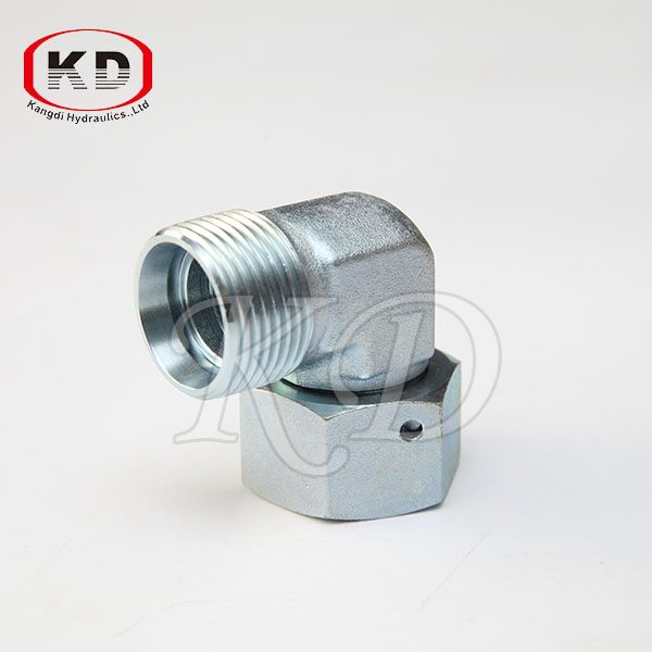
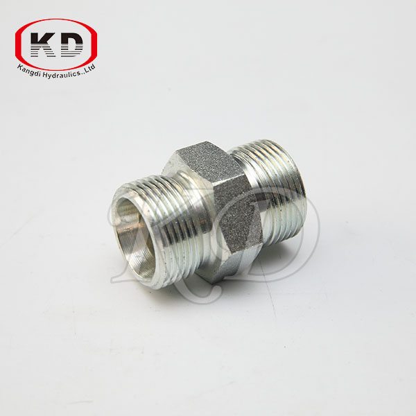
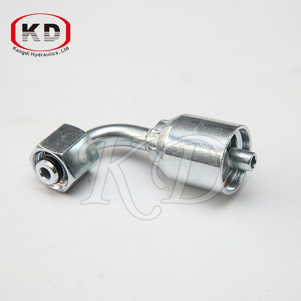
Product detail pictures:
Related Product Guide:
Importance of PVC Fittings
Things to Know About Pipe Fitting Works
We also provide item sourcing and flight consolidation solutions. We have now our very own manufacturing facility and sourcing place of work. We could provide you with nearly every kind of merchandise associated to our merchandise variety for China Wholesale for 15611-PO Sockeless Hose Fitting for Peru Manufacturers, The product will supply to all over the world, such as: Juventus, Amman, Greek, We are committed to meet all your needs and solve any technical problems you may encounter with your industrial components. Our exceptional products and vast knowledge of technology makes us the preferred choice for our customers.
Visit our Custom Tubes, Hoses and Brake Lines Center in Indianapolis, IN at 3140 West Morris Street for repair or fabrication of virtually any fluid line for any application. Types of assemblies we manufacture are as follows: Hydraulic Hose, Metal Tube, Teflon Braided Hose, Fuel Injection Systems, Air Conditioning, Power Steering, Brake Systems and custom DOT approved brake hoses in our BrakeQuip Department.
Lab experiment demonstrating the energy losses associated with flow through various hydraulic fittings.
Laboratory Experiment 13: Local Losses
ENGR 318 — Fluid Mechanics
Purpose
To experimentally determine the local loss “k” values for several different pipe fittings, and compare them to known, ‘typical’ k values for these same fittings.
Background
In addition to energy loss due to boundary friction in pipes, losses in energy can also be attributable to instantaneous losses due to changes in pipe geometry or diameter, and as water flows through a variety of different turbulence-inducing fittings. These instantaneous, minor losses also occur at the entrances and exits of pipe sections that interact with tanks or reservoirs.
Minor losses can be expressed in terms of head:
Where ho = local loss (m)
V = average flow velocity (m/s)
g = gravitational acceleration (m/s2)
k = loss coefficient (unitless)
Minor loss coefficients have been established for a variety of different fittings and flow geometries, although variation exists as a function of factors such as diameter, weld type, material, manufacturer, etc. The fittings to be tested in this experiment, along with typical k values, are shown in Table 1 below. In cases of an expansion or contraction between two pipes, the head loss can either be calculated by multiplying a loss coefficient by an upstream or downstream velocity head (depending on convention).
In this experiment, pressure differences will be measured to determine local losses. Specifically, local loss ho can be measured experimentally by:
Where Δp = measured pressure change across fitting (N/m2)
γ = unit weight of water (N/m3)
Table 1 — Typical k values for different fitting types, along with position number on the pipe rack (see Figure 1), and which pipe / flow path each fitting lies along.
Fitting Position Number Pipe Location Typical K
45-degree “Y” 4 A 0.76
Long radius 90-degree bend 6 A 0.4
Ball valve 12 A 0.04 — 0.1 (fully open)
90-degree “T” 13 A 1.8
90-degree mitre 14 A 1.7
Short radius 90-degree bend 15 A 0.2
Gate Valve 21 A 0.03 — 0.2 (fully open)
45-degree elbow 5 B 0.7
90-degree elbow 22 B 0.9
Globe valve 20 B 3 — 10 (fully open)
Sudden contraction 3 C 0.4 (X outgoing velocity head)
Sudden enlargement 16 C 0.7 (X incoming velocity head)
Experimental Procedure:
1. Establish a constant flow through the experimental apparatus, and ensure that all air has been expelled from the system by observing flow through the venturimeter.
2. Measure the actual flow rate through the apparatus by collecting a volume of water in the discharge tank and recording the time in which collection took place.
3. Using the pressure meter, measure the pressure loss between the two pressure taps for the fitting being analyzed.
4. Repeat using the other fittings in the network.
5. Measure the temperature of the water.
Report
• For each fitting, calculate a k value for each flow rate using the pressure loss information obtained in lab. Also compute the average k value for each fitting.
• Compare between experimental k values (determined by lab measurements) and the typical k values that are provided.
• Include a summary table of results in the body text. Also attach a printout of your excel calculations as an appendix to the report, including a row explaining how each column in the spreadsheet was calculated.
• In the discussion of results, identify which fittings had experimental k values that varied considerably from the typical k values that were provided. Attempt to explain the source of these differences, in terms of what’s happening inside of the fitting.
• Include a brief section in the report addressing your impression of the “virtualized” aspect of this experiment. In what ways is a virtualized experiment better than an in-person lab? In what ways is it worse? What other comments / impressions do you have about delivering lab-related content in this way?
Figure 1 — Armfield Pipe Rack Apparatus.
Flow Flow Path Pipe Dia. (mm) Fitting # Δp (kPa) Volume collected (L) Time (s)
High A 17 45-degree “Y” 4
A 17 Long radius 90° bend 6
A 17 Ball valve 12
A 17 90-degree miter 14
A 17 90-degree “T” 13
A 17 Short radius 90° bend 15
A 17 Gate Valve 21
B 17 45-degree elbow 5
B 17 90-degree elbow 22
B 17 Globe valve 20
C 17/8 Sudden contraction 3
C 8/17 Sudden enlargement 16
Low A 17 45-degree “Y” 4
A 17 Long radius 90° bend 6
A 17 Ball valve 12
A 17 90-degree “T” 13
A 17 90-degree mitre 14
A 17 Short radius 90° bend 15
A 17 Gate Valve 21
B 17 45-degree elbow 5
B 17 90-degree elbow 22
B 17 Globe valve 20
C 17/8 Sudden contraction 3
C 8/17 Sudden enlargement 16
The company has rich resources, advanced machinery, experienced workers and excellent services, hope you keep improving and perfecting your products and service, wish you better!